| General Diesel Information |
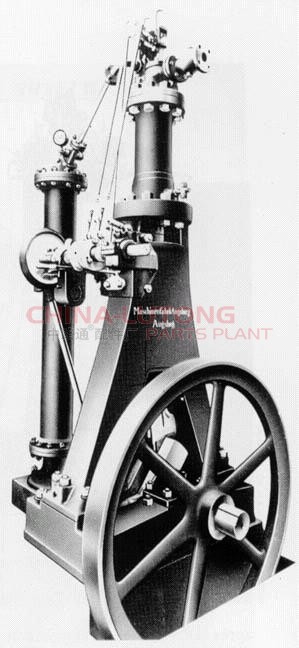
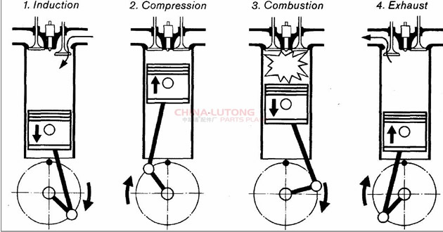
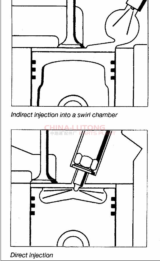
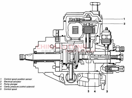
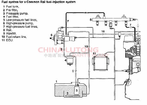
Diesel History:Rudolf Diesel invented the first commercially-successful compression-ignition engine at the end of the 19th century. Compared with the spark ignition engine, the diesel had the advantages of lower fuel consumption, the ability to use cheaper fuel, and the potential for much higher power outputs. Over the following two or three decades, such engines were widely adopted for stationary and marine applications, but the fuel injection systems used were not capable of high-speed operation. This speed limitation and the considerable weight of the air compressor needed to operate the injection equipment, made the first diesel engines unsuitable for use in road-going vehicles. In the 1920s, the German engineer Robert Bosch developed the in-line injection pump, a device which is still in extensive use today. The use of hydraulic systems to pressurise and inject the fuel did away with the need for a separate air compressor, and made possible much higher operating speeds. The so called ˇ®high-speedˇŻ diesel engine became increasingly popular as a power source for goods and public transport vehicles, but for a number of reasons (including specific power output, flexibility and cheapness of manufacture), the spark-ignition engine continued to dominate the passenger car and light commercial market. In the 1950s and 60s, diesel engines became increasingly popular for use in taxis and vans, but it was not until the sharp rises in oil prices in the 1970s that serious attention was paid to the small passenger car market. VWˇŻs introduction of the diesel-powered Golf at the end of 1977 marked the arrival of the first ˇ®user-friendlyˇŻ diesel car, designed specifically to be acceptable to drivers who would not previously have considered abandoning the petrol engine. The diesel engine fitted to the Golf used indirect injection and a distributor type pump, and was comparable in performance to the smaller petrol engines fitted to the range. Subsequent years have seen the growing popularity of the small diesel engine in cars, 4WDˇŻs and light commercial vehicles, not only for reasons of fuel economy and longevity, but also for environmental reasons. Every major European car manufacturer now offers at least one diesel-engined model. The dieselˇŻs growth in the Australian market has been relatively slow (due in part to the lack of any considerable fuel price differential in favour of diesel which exists in other parts of the world), but it has now gained widespread acceptance, and this trend looks set to continue. Direct and indirect injection:In practice, it is difficult to achieve smooth combustion in a small-displacement engine by injecting the fuel directly into the combustion chamber. To get around this problem, the technique of indirect injection is widely used. With indirect injection, the fuel is injected into a pre-combustion or ˇ®swirlˇŻ chamber in the cylinder head, alongside the main combustion chamber. During the compression stroke the compressed hot air is forced into the swirl chamber where it enters a rapid swirling motion; fuel is injected into the swirl chamber, where it mixes with the rapidly moving air, enabling smoother combustion in the main combustion chamber. Generally speaking, indirect injection engines are less efficient than direct injection engines, and also require more preheating when starting from cold, but these disadvantages are offset by smoother and quieter operation. Until recently, direct injection engines were mostly fitted to light commercial vehicles, where increased noise and harshness are considered acceptable trade-offs for improved fuel economy. Recently, the use of electronic diesel engine control systems, such as common-rail, has allowed the development of more refined direct injection engines, and their use in smaller diesels for passenger vehicles is now almost universal. Electronic Diesel Control systems:Development of the diesel engine, and particularly the fuel injection system, has been relatively slow compared with the advances which have been made in petrol engine fuel injection and management systems. However, in recent years, electronic diesel engine control systems have been developed to improve diesel engine efficiency and to reduce exhaust emissions. Almost all modern engines use some form of electronic engine control system. For a diesel engine to operate efficiently, it is essential that the correct amount of fuel is injected at the correct pressure, and at exactly the right time. Even small deviations can cause increased exhaust emissions, increased noise, and increased fuel consumption. In a typical diesel engine, the injection process takes only one thousandth of a second, and only a minute quantity of fuel is injected. Electronic control using a conventional fuel injection pumpThe sole function of the fuel injection pump is to supply diesel fuel to the injectors at the correct pressure, at the correct moment in the combustion cycle, and for the length of time necessary to ensure efficient combustion. A conventional (mechanically-controlled) fuel injection pump uses an accelerator cable (connected to the driverˇŻs accelerator pedal), and various mechanical add-on devices (such as cold start injection advance, fast idle units, etc). Even with these add-on devices, it has become increasingly difficult for a mechanical diesel control system to keep pace with modern demands on engine refinement and exhaust emission control. Many electronic diesel engine control systems use a conventional in-line or distributor fuel injection pump, but the injection pump timing and the quantity of fuel injected are controlled electronically instead of mechanically. Various electronic sensors are used to measure variables such as accelerator pedal position, engine crankshaft speed, engine camshaft position, the mass of air passing into the engine, turbocharger boost pressure, engine coolant temperature, ambient air temperature, etc. The information from these various sensors is passed onto an electronic control unit (ECU), which evaluates the signals. The ECU memory contains a series of mapped values for injected fuel quantity, and start-of-injection point. The ECU performs a number of calculations based on the information provided by the sensors, and selects the most appropriate map for the fuel quantity and start-of-injection point from its stored values. The ECU is capable of analysing the data and performing calculations many times per second, which allows very accurate control over the operation of the engine. Electronically controlled mechanical injection pump High Speed solenoid controlled distributor fuel-injection pumps VE-MVOn the electronic solenoid valve controlled distributor pumps, the fuel injection is controlled by a high-pressure solenoid valve. This permits an even higher degree of flexibility in the fuel metering and in the variability of the start of injection. This system also incorporates a pump mounted ECU on the upper side of the pump and uses hybrid other techniques. In addition to the mechanical loading with which it is confronted in the vehicleˇŻs under-hood environment, the pump must also fulfil the following assignments: ˇŞ Data exchange with the separately mounted main ECU ˇŞ Evaluation of the signal from the angle-of-rotation sensor ˇŞ Triggering of the high-pressure solenoid valve & timing device, Maps are stored in the pump ECU which not only take into account the setting points for the particular vehicle application and certain engine characteristics, but also permit the ability of the received signals to be checked. The high pressure generated in the high pressure chamber (the fuel from the supply pump is compressed by the axial piston when this is forced up by the cam plate riding over the rollers of the roller ring) opens the delivery valve and the fuel is forced through the pressure line to the injector. Injection pressure at the nozzle is 1400 bar. Excess fuel is directed back to the tank through return lines. If the high-pressure solenoid valve should fail, fuel injection stops. This prevents uncontrolled ˇ°racingˇ± of the engine. Solenoid valve controlled injection pump using electronic control (VP44) Electronic control using Common-rail diesel injection systemsThe common rail system derives its name from the fact that a common rail, or fuel reservoir, is used to supply fuel to all the fuel injectors. This technology is similar to what EFI petrolˇŻs have been using for many years. Instead of an in-line or distributor fuel pump, which distributes the fuel directly to each injector, a high-pressure pump is used, which generates a very high fuel pressure (up to 2000 bar on some systems) in the accumulator rail. The accumulator rail stores fuel, and maintains a constant fuel pressure (via a fuel pump), with the aid of a pressure control valve. Each injector is supplied with high-pressure fuel from the accumulator rail, and the injectors are individually controlled via signals from the systems electronic control unit. The injectors are electromagnetically operated. The components can be divided into three sub-systems: the low-pressure fuel system, the high- pressure fuel system and the electronic control system. Low-pressure fuel system:Fuel tank, Fuel lift pump, Fuel filter/water trap, Low-pressure fuel lines, Fuel cooler. The low-pressure system (fuel supply system) is responsible for supplying clean fuel to the high-pressure fuel circuit. High-pressure fuel system:High-pressure fuel pump with pressure control valve, High-pressure accumulator rail with fuel pressure regulator, Fuel injectors, High-pressure fuel lines.
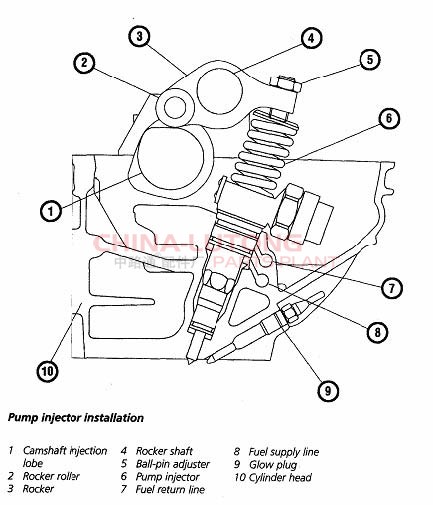
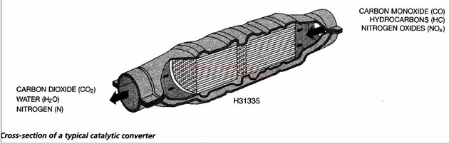
After passing through the fuel filter, the fuel reaches the high-pressure pump, which forces it into the accumulator rail, generating pressures of up to 1350 bar. Since diesel fuel has a certain elasticity, the pressure in the accumulator rail remains constant, even though fuel leaves the rail each time one of the injectors operates: additionally, a pressure control valve mounted on the high-pressure pump ensures that the fuel pressure is maintained within pre-set limits. The pressure control valve is operated by the ECU. When the valve is opened, fuel is returned from the high- pressure pump to the tank, via the fuel return lines, and the pressure in the accumulator rail falls. To enable the ECU to trigger the pressure control valve correctly, the pressure in the accumulator rail is measured by a fuel pressure sensor. The electromagnetically-controlled fuel injectors are operated individually, via signals from the ECU, and each injector injects fuel directly into the relevant cylinder. The fact that high fuel pressure is always available allows very precise and highly flexible injection in comparison to a conventional injection pump: for example combustion during the main injection process can be improved considerably by the pre-injection of a very small quantity of fuel. ˇ®Unit InjectorˇŻ (Pumpe Deuse) systemsThe ˇ®pump injectorˇŻ system has been in use in basic form for some years on larger direct injection diesel engines. Recent developments in electronic engine control systems have enabled the system to be refined for use on smaller car and light commercial engines, with VW/Audi, and Land Rover among the major manufacturers selling vehicles equipped with this system. As its name implies, a ˇ®pump injectorˇŻ consists of a fuel injection pump, combined with a fuel injector. Each cylinder of the engine has its own pump injector, which eliminates the need for a separate high-pressure fuel pump, and the associated high-pressure fuel lines and rail. The pump injectors are operated by the engine camshaft, and are able to generate extremely high fuel pressures (up to 2000 bar on some systems). The pump injectors are mounted in the cylinder head, and are supplied with fuel via a distributor pipe mounted in the cylinder head. A fuel lift pump pumps fuel from the fuel tank to the distributor pipe. Each pump injector is individually controlled via signals from the vehicles electronic control unit (ECU). The pump injectors are electromagnetically-operated. Pressure limiting valves maintain constant fuel pressures in the fuel supply and return lines. Because of the extremely high fuel injection pressure, the fuel in the return line becomes very hot, and a fuel cooling system is used to cool the excess fuel before it is returned to the tank. Besides the obvious effect on safety, if the fuel was not cooled, the fuel temperature in the tank would rise, which in turn means that the temperature of the fuel supplied to the injectors would also rise. Under high-pressure injection conditions, hot fuel reduces fuel delivery from the injectors; although the ECU can compensate to a reasonable degree for fuel temperature variations, cool fuel gives improved combustion and hence improved engine efficiency. Electronic Control Unit (ECU):The electronic control system consists typically of the following components: Electronic control unit (ECU), Fuel lift pump, Crankshaft speed/position sensor, Camshaft position sensor, Accelerator pedal position sensor, Turbocharger boost pressure sensor, Air temperature sensor, Coolant temperature sensor, Air mass meter, Fuel pressure sensor, Fuel injectors, Fuel pressure control valve, Preheating control circuit, EGR valve actuator. The information from the various sensors is passed to the ECU, which evaluates the signals. The ECU contains electronic ˇ®mapsˇŻ which enable it to calculate the optimum quantity of fuel to inject, the appropriate start of injection, and even pre- and post injection fuel quantities, for each individual engine cylinder under any given condition of engine operation. Additionally, the ECU carries out monitoring and self diagnostic functions. Any faults in the system are stored in the ECU memory, which enables quick and accurate fault diagnosis using appropriate diagnostic equipment (such as a suitable fault code reader). Turbocharging:Turbochargers have long been used on large diesel engines, and are becoming common on small ones. The turbocharger uses the energy of the escaping exhaust gas to drive a turbine which pressurises the air in the inlet manifold allowing more air to be present. More air means more fuel can be burnt and more power can be developed from the same size engine. Additional benefit can be gained from turbocharging if the pressurised air is cooled before it enters the engine. This is done using an air-to-air or air to water to air heat exchanger called an intercooler. An intercooler lowers the air between the turbo and the engine. The cooled air is denser and contains more oxygen in a given volume than warm air straight from the turbocharger. On the increase of late is the use of a variable geometry turbocharger (VNT). With this design, the exhaust gasses entering the turbocharger pass through a variable size venturi. When the engine speed is low and the exhaust gas speed is slow, the venturi diameter is reduced. This has the effect of speeding up the gasses just before they meet the turbocharger wheel. This maintains a high turbine speed, which improves turbocharger performance at low engine speeds. At higher engine speeds when the gasses are moving much faster, the venturi is enlarged. Using this system allows the turbocharger to operate at close to maximum efficiency at a greater range of engine speeds than a standard waste gate controlled turbo. Fuel cooling systems:Fuel cooling is present on some rotary pump systems and nearly always on common rail or unit injection diesel systems. The fuel cooling system is separate from the engine cooling circuit, because the temperature of the engine coolant is too high to cool the fuel when the engine is at operating temperature. In most cases, the fuel coolant circuit is connected to the main coolant expansion tank, but in such a way that the hotter engine coolant circuit has no adverse effect on the fuel coolant circuit. The connection to the expansion tank allows the system to be filled, and also allows for expansion of the coolant with varying temperature. In some situations a separate air to fuel cooler may be used. A fuel cooler may be mounted on the fuel filter head. The fuel cooler is basically a fuel/coolant heat exchanger. Cold coolant is pumped through the cooler by an electric pump, controlled by the engine ECU. As the coolant passes through the cooler, it absorbs heat from the fuel. The cooled fuel then passes to the fuel tank, while the warm coolant passes to a radiator at the front of the vehicle. The radiator, which is separate from the engine cooling system radiator, is cooled by the air passing through it due to the forward motion of the vehicle, supplemented by air from the engine cooling fan(s) when necessary. The cold coolant then passes to the coolant pump, and the cycle starts again. The other type of system used is similar to a hydraulic transmission cooler being a liquid to air style cooler. Exhaust emissions:Because combustion in a correctly-functioning diesel engine nearly always occurs in conditions of excess oxygen, there is little or no carbon monoxide (CO) present in the exhaust gas. A further environmental benefit is that there is no added lead in diesel fuel. For many years, there was no need for complicated emission control systems on diesel engines, in the last few years however simple catalytic converters, and exhaust gas recirculation systems, have become standard on most diesel engines in order to meet the increasingly stringent emission regulations. The advent of electronic diesel engine control systems has also helped to improve diesel engine emissions. Catalytic converterThe catalytic converter consists of a canister containing a fine mesh impregnated with a catalyst material, over which the exhaust gases pass. The catalyst speeds up the oxidation of harmful carbon monoxide and unburnt hydrocarbons, effectively reducing the quantity of harmful products reaching the atmosphere (see illustration). Because unburnt hydrocarbons contribute to particle emission, this can also be reduced to a limited extent by a catalytic converter. A closed-loop catalytic converter system using an oxygen sensor, similar to that used on petrol engines, cannot be used on a diesel engine because a diesel engine always operates with excess air, and hence oxygen, in the exhaust gas.
Diesel Fuels:Diesel-fuel componentsDiesel fuels consist of a large number of hydrocarbons which have boiling points in the range between about 180ˇăC and 370 ˇăC. They are obtained by the step-wise distillation of crude oil. Refineries are increasingly adding con version products (crack components) to diesel fuels. These are obtained from heavy oils by using fission (cracking) of larger modules into smaller ones by the application of heat, pressure, and catalysts. Characteristic valuesThe requirements placed on diesel fuels are defined in national standards. The EN 590 standard applies in Europe, and DIN 51 601 in Germany. The most important parameters as stipulated in these standards are given below: Cetane number, ignition quality.Since the diesel engine operates without externally supplied ignition, following its injection into the hot, com pressed air in the combustion chamber, the diesel fuel must ignite of its own accord with the minimum possible delay (ignition lag). Ignition quality is defined as that property of the fuel which serves to initiate diesel engine ignition. Ignition quality is expressed by the cetane number (CN). The higher the cetane number, the easier it is for the fuel to ignite. Cetane, which has very good ignition qualities, is assigned the cetane number 100, whereas methyl naphthalene, which features poor ignition qualities, is given the cetane number 0. DIN 51 601 specifies a minimum cetane number of 45 for diesel fuels. However, higher cetane numbers of around 50 are desirable for optimum operation of modern engines (quiet running, particulate emissions). High quality diesel fuels contain a large proportion of paraffins with high CN numbers. In contrast, aromatics of the kind found in crack components impair ignition quality. Cold behaviour, filterabilityAt low temperatures, the precipitation of paraffin crystals can cause clogging of the fuel filter, and thus result in interruption of the fuel supply. The start of paraffin precipitation can be as early as 0ˇăC in most cases. Consequently, winter diesel fuels must be specially selected, or treated, in order to guarantee problem free operation in cold weather. Normally, ˇ°flow improversˇ± are added at the refinery. Although these do not prevent precipitation of the paraffins, they limit the crystal growth to a very high degree. The crystals that do form are so small that they can still pass through the filter pores. As a result, filterability can be extended down to lower temperatures. In accordance with DIN 51 601, filterability should be guaranteed down to at least -15ˇăC. The resistance to cold can be improved even further by additives which prevent precipitation of paraffin crystals. The win ter diesel fuels which are widely available today guarantee cold resistance down to at least -22 ˇăC. Additional measures are the addition of petroleum to the diesel fuel. Admixing of regular grade petrol can also delay crystal precipitation; however, the ignition quality is impaired and the flash point considerably reduced (petrol has very low cetane numbers). Today, if correct fuels are used as stipulated by Australian standards, such additives are no longer necessary. Flash pointThe flash point is the temperature at which a combustible liquid gives off just enough vapour to the air surrounding it that the vapour/air mixture above the liquid can be ignited by an ignition source. Diesel fuels have a flash point above 55ˇăC. For example, petrol content of less than 3% in the diesel fuel can reduce the flash point to such an extent that ignition is possible at room temperature. Boiling rangeThe position of the boiling range influences parameters which are important for the operating behaviour of the diesel fuel. Although extension of the range towards lower temperatures leads to a fuel which is suitable for cold operation, the cetane number is reduced at the same time, and this impairs the lubrication properties in particular. However, poorer lubrication properties increase the risk of fuel-injection equipment wear. If, on the other hand, the final boiling point temperature is increased, which is desirable in order to achieve better utilization of crude oil, this can lead to increased soot production and nozzle coking (deposit of combustion residues). DensityThe diesel fuelˇŻs calorific value depends on a good approximation to its density, and increases with increasing density. Therefore, if fuels with greatly differing densities are used with the fuel injection pump kept at the same setting, (volume metering by the pump is constant), shifts occur in the mixture composition owing to the fluctuations in the calorific values, which in turn leads to increased soot emission for high densities, and a reduction in output power for low densities. SulphurDiesel fuels contain sulphur in chemically bound form, depending on the crude-oil quality and the components used in the mixture. Crack components in particular have high sulphur contents, but these can be reduced by treatment with hydrogen at the refinery. Since sulphur is converted into sulphur dioxide (SO during combustion in the engine (this substance is environmentally hostile owing to its acidic reaction), maximum permitted sulphur content is limited by law. It has been reduced in several stages in recent years, and since 1 Oct 1996 must not exceed 0.05% by weight in Europe. Of course in Australia we are still waiting to see these low levels 10 year later!! The intention is to reduce the mass of emitted particulates which, in the case of catalytic exhaust gas aftertreatment, also contain sulphates in addition to soot. AdditivesQuality improvement by the addition of additives, as has been common practice with petrol for years now, has recently also become popular overseas for diesel fuels (ˇ°super-gradeˇ± or ˇ°premium-gradeˇ± diesel fuel). Additive packages are mostly used which have a multiple effect: -Ignition improvers raise the cetane number and are responsible in particular for quieter combustion. -Detergents to prevent nozzle coking. -Corrosion inhibitors to prevent corrosion of metal parts (in the event of water being entrained into the fuel system). ˇŞ Anti-foaming agents to facilitate tank filling. The overall concentration of additives is generally below 0.1%, so that the physical characteristics of the fuel, such as density, viscosity, and boiling curve do not change. BioDiesel:BioDiesel is the name for a variety of ester-based oxygenated fuels made from vegetable oils or animal fats. The concept of using vegetable oil as a fuel dates back to 1895 when Dr. Rudolf Diesel developed the first diesel engine to run on vegetable oil. Diesel demonstrated his engine at the World Exhibition in Paris in 1900 using peanut oil as fuel. It is generally made from domestically produced, renewable oilseed crops such as soybeans, canola, cotton seed and mustard seed. In general, biodiesel will soften and degrade certain types of elastomers and natural rubber compounds over time. Using high percent blends can impact fuel system components (primarily fuel hoses and fuel pump seals), that contain elastomer compounds incompatible with biodiesel. Manufacturers recommend that natural or butyl rubbers not be allowed to come in contact with pure biodiesel. Biodiesel will lead to degradation of these materials over time. Cold weather can cloud and even gel any diesel fuel, including biodiesel. Users of a 20 percent biodiesel blend will experience a decrease of the cold flow properties (cold filter plugging point, cloud point, pour point) of approximately 2-3ˇŻC. Neat (100 percent) biodiesel will gel faster than petrodiesel in cold weather operations. |